The design question
How do building form and openings change the path of incoming wind? A favorable change in one area can leave another room weakly ventilated.
CFD CONSULTING · RESIDENTIAL DESIGN · 2022
Connecting the external wind, the path through the rooms and the building's solar exposure—so a floor-plan comparison has a physical explanation.
MY WORKPrepared and meshed supplied geometry, defined the CFD scenarios, ran airflow and solar analyses, checked results across tools and produced the engineering comparisons. A collaborator handled client-facing coordination.
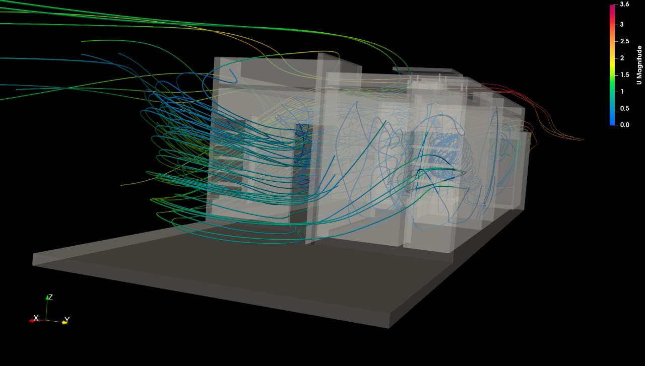
CONSULTING STUDY / ARCHITECTURAL COMPARISON
How do building form and openings change the path of incoming wind? A favorable change in one area can leave another room weakly ventilated.
I prepared the supplied geometry, defined and ran airflow scenarios, examined room-level circulation and assessed solar exposure separately.
The figures explain local flow paths and trade-offs for design discussion. The solar views add a separate exposure assessment rather than a claimed annual energy saving.
An independent residential consulting case, not an industrial demonstration from the professional log. Client coordination was collaborative; CFD preparation, analysis and engineering figures were my contribution.
01 / THE DESIGN QUESTIONS
The architectural team needed to compare the existing and modified floor plans before finalizing the design. Flow distribution and solar exposure were complementary parts of that decision.
The workflow began with geometry cleanup and solidification, followed by an external domain connecting the wind field to the interior through the actual door and window openings.
Airflow was studied in OpenFOAM, with selected Fluent cross-checks. Solar heat-flux exposure was analyzed separately in Fluent on the building envelope. Both work streams informed the same design comparison.
The continuous wind problem was reduced to two opposing directions and three representative speeds. Applying that matrix to both floor plans exposes whether a design depends on one favorable wind condition.
The post-processing planes were selected around usable openings: one plan view and vertical sections through the entrance, bedroom doors and front window.
| Design | Wind direction | Approach speeds | Read-out |
|---|---|---|---|
| Base | Two directions, 180° apart | 2.5 / 3.5 / 4.5 m/s | Plan and opening-aligned sections |
| Modified | Same two directions | Same three speeds | Corresponding flow-distribution views |
Why twelve cases: the purpose is to separate geometry, direction and speed effects—not to rank designs from a single attractive contour.
02 / THE ROOM-LEVEL COMPARISON
Wind enters as a concentrated jet and travels between openings. Rooms away from that pressure-driven path develop slower, recirculating flow.
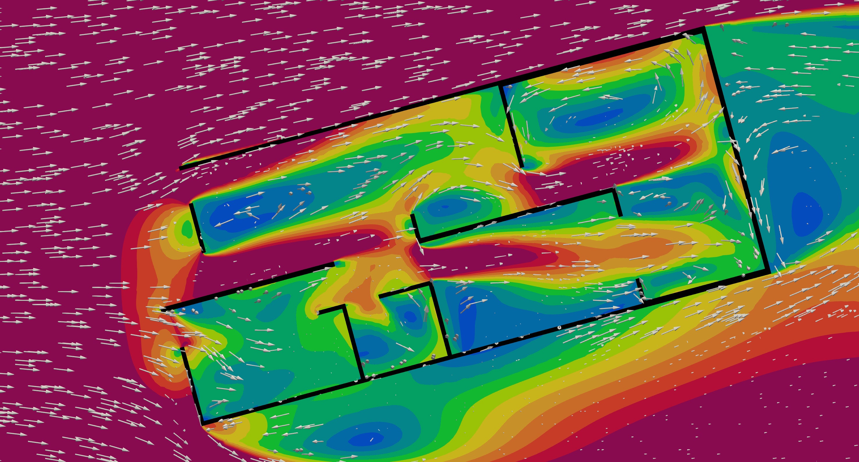
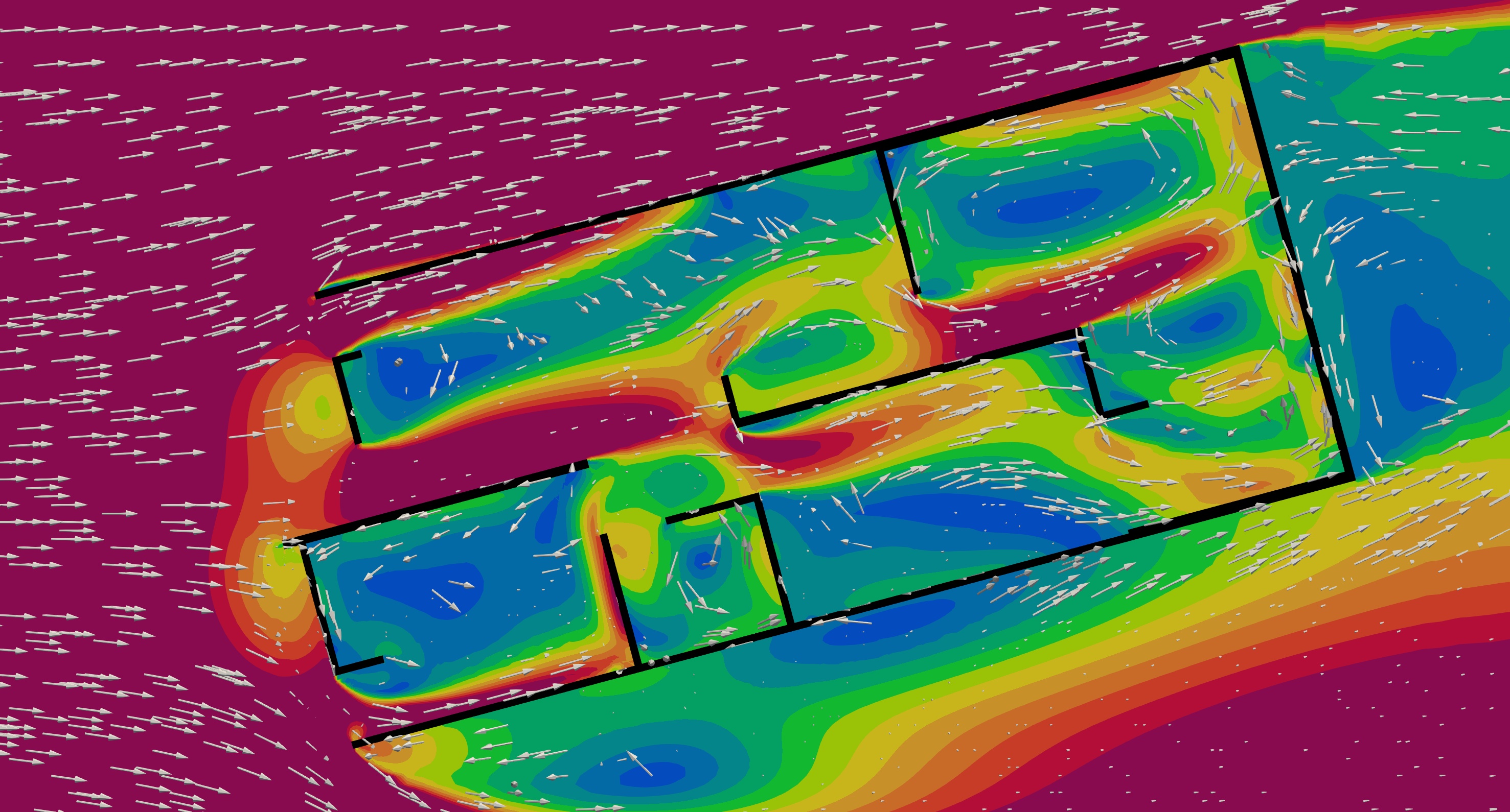
The modified layout changes which rooms lie on the main through-flow path. It redistributes ventilation instead of increasing velocity uniformly everywhere.
This matters to a design team because “more open area” is not a complete prescription: the position and connection of those openings determine where the momentum goes.
Internal partitions are not symmetric. Reversing wind direction changes the recirculation pattern rather than simply mirroring the original result.
The useful design comparison therefore asks which rooms are prioritized under each direction. A single global “better design” number would hide that decision.
03 / THE MECHANISM BEHIND THE PLAN VIEW
The plan view shows where air moves. Vertical sections add the mechanism: an entrance jet, roof-edge separation and the interaction between the external flow and the interior.
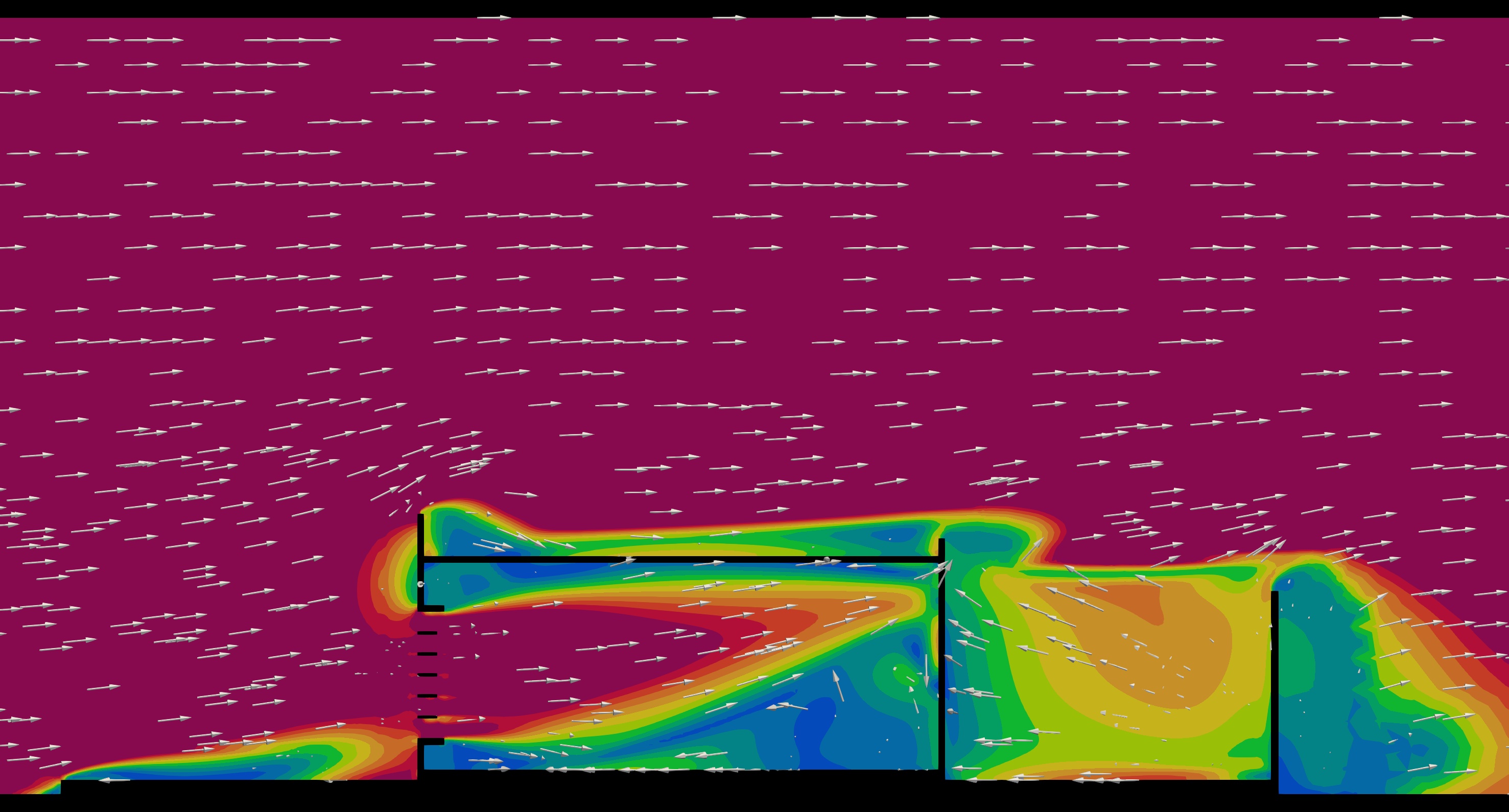
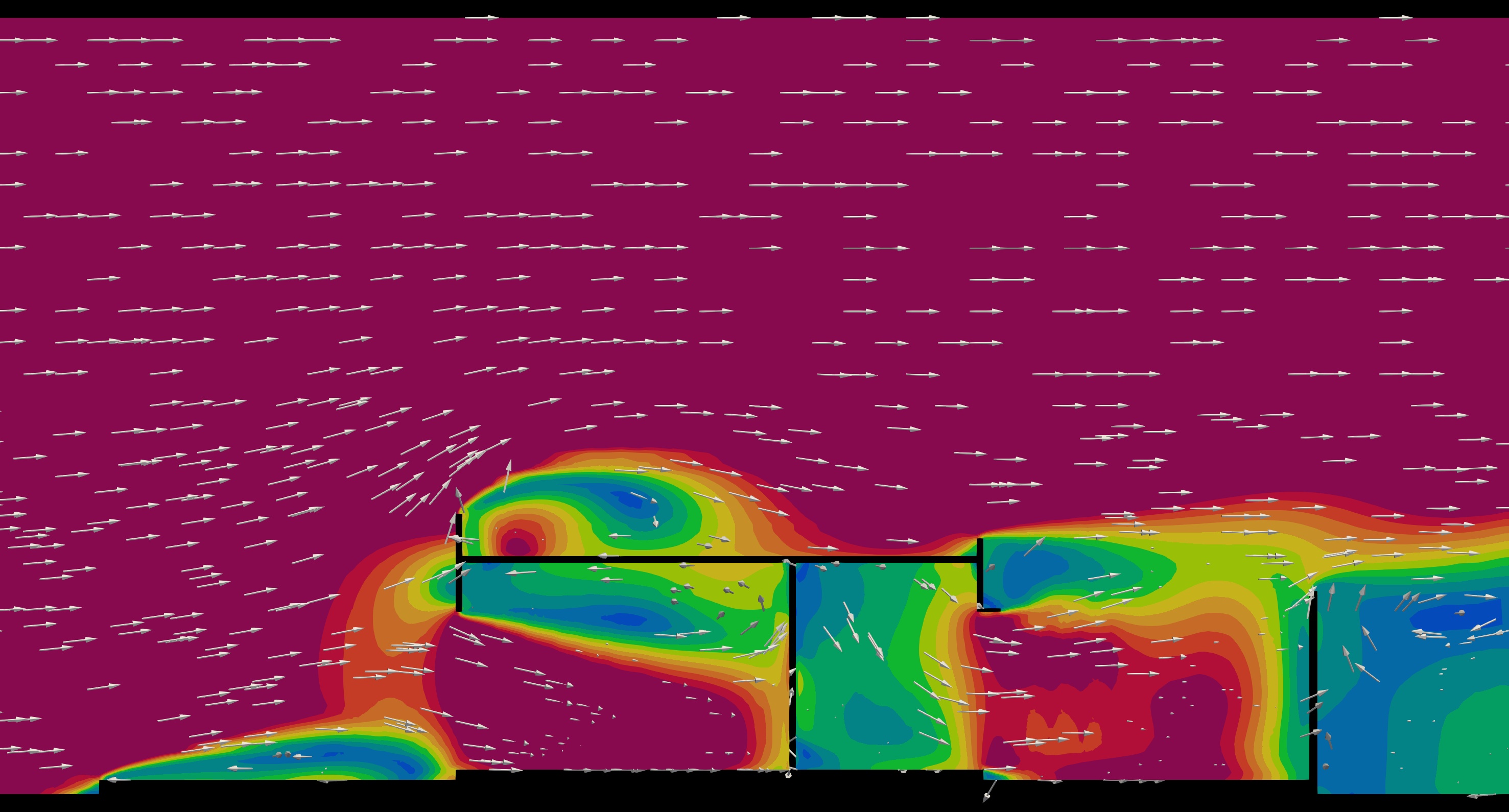
The correspondence between horizontal and vertical cuts is also a quality check: the interpretation should agree across views, rather than depend on one convenient slice.
04 / BEYOND A SINGLE BUILDING
A companion study examined two houses under candidate site orientations. It extends the geometry question from an individual floor plan to the surrounding exposure.
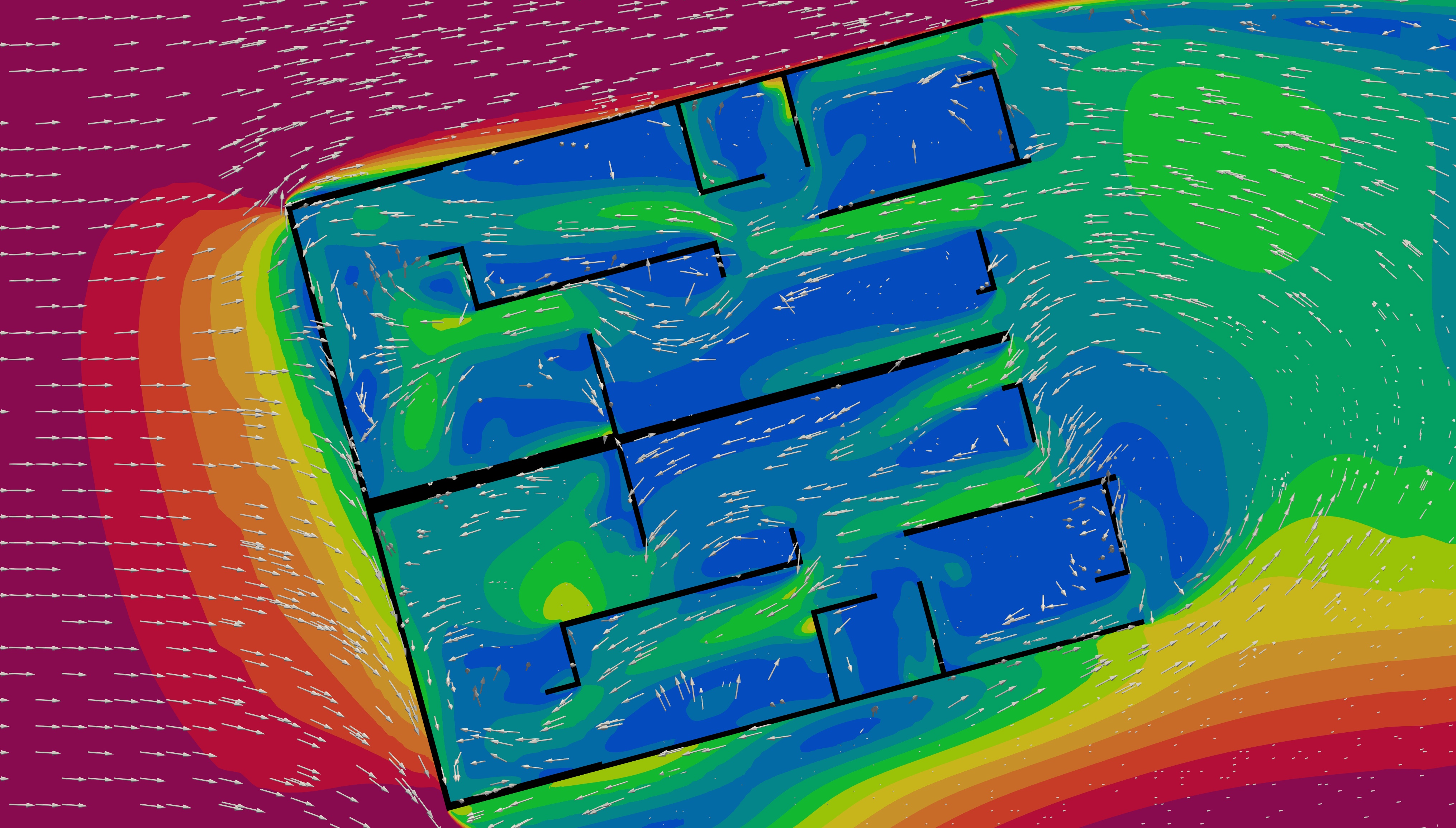
A nearby building changes the flow approaching an opening. Wake sheltering and channeling mean that an isolated-building assumption may miss the exposure relevant to the actual site.
The paired-house study compared orientation options and inspected the flow around and between both buildings. It demonstrates the need to choose the computational domain around the engineering question.
The available record supports the comparison method and visual interpretation, but not a recovered final winning orientation.
05 / SOLAR HEAT-FLUX EXPOSURE
The thermal work stream examined direct solar heat flux on the building envelope, adding a second physical consequence to the architectural geometry comparison.
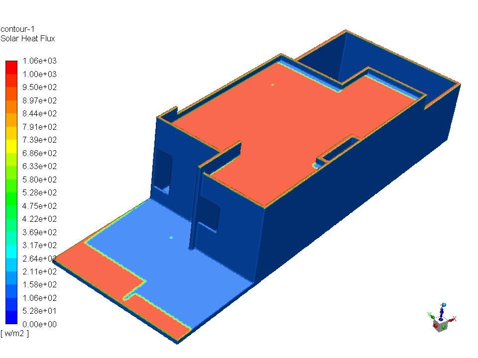
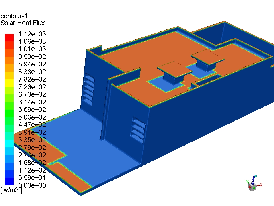
Sun-facing roof surfaces carry high direct flux while shaded walls are near the low end of the scale. Roof steps, parapets and the modified massing alter which surfaces shade one another.
The original images show heat-flux scales of roughly 1.0–1.1 kW/m². Those are surface-exposure levels under the plotted solar scenarios, not whole-building energy consumption.
Changing the openings and roof form affects both ventilation paths and solar exposure. The comparison gives the architectural team a physical basis for discussing the competing effects.
It does not turn the two analyses into a verified annual comfort or energy model. Their value here is a design-stage explanation of flow distribution and envelope exposure.
Engineering delivery: turn geometry changes into understandable consequences—where the air goes, why recirculation appears, and which surfaces the building shades.
WHAT THIS WORK BRINGS TO ANOTHER PROJECT
The consulting experience combines model preparation, physical interpretation and communication with a team that does not work in CFD.
Cleaned supplied CAD and connected an external flow domain to the occupied interior; included neighboring geometry when exposure mattered.
Transfer: Preparing useful flow domains from design geometry in equipment, HVAC and external-aerodynamics studies.
See the engineering evidence ↑Varied layout, direction and speed, and compared corresponding plan and section views.
Transfer: Structuring design comparisons so operating-condition sensitivity is not mistaken for geometric improvement.
See the engineering evidence ↑Examined direct heat flux and self-shading on a complex envelope in Fluent.
Transfer: Thermal exposure studies for buildings, enclosures and equipment, with application-specific thermal modeling.
See the engineering evidence ↑Used OpenFOAM with selected Fluent checks and explained jets, recirculation and shading through targeted views.
Transfer: Detecting inconsistent results and communicating engineering trade-offs to non-CFD design teams.
See the engineering evidence ↑Exact turbulence closure, final mesh statistics and absolute building dimensions are not established in the retained documentation. The evidence does not establish air-change rates, percentage improvement, annual energy savings or occupant-comfort indices. No final client recommendation memo is reproduced.
Only anonymized result renderings are used. The 3D streamline hero was explicitly supplied by the author for this revision; its exact scenario mapping is not assigned here. Geometry/CAD, addresses, client identities and private communications remain excluded.
CFD and selected results: Alberto Brambila Solórzano. Supplied architectural geometry and client coordination were part of the consulting collaboration.
Implementation files and detailed configurations are maintained privately. This page presents the engineering approach and selected evidence.
© 2026 Alberto Brambila Solórzano. All rights reserved.